The Thermoptim software package provides a modeling environment integrating in a deeply interconnected way a diagram editor / synoptic screen, interactive charts, simulation functions and an optimization method based on the pinch method. Its objective is twofold: to facilitate and secure the modeling of energy conversion technologies.
Main simulator features
Thermoptim allows one to calculate the complete state of different fluids (temperature, pressure, mass volume, enthalpy, internal energy, entropy, exergy and quality), for ideal gases and condensable vapors. These fluids can undergo various transformations or processes:
-
compression and expansion, in open or closed systems. These can be adiabatic or polytropic, and are characterized by their isentropic or polytropic efficiency ;
-
combustion, also in a closed or open system, at set pressure, volume or temperature. Fuel can be introduced into the combustion chamber separately from the oxidizer, or premixed. The dissociation of the carbon dioxide can be taken into account ;
-
isenthalpic throttling ;
-
heat exchanges with other fluids: the software is able to calculate the UA product or the overall heat transfer coefficient across the surface of a heat exchanger for the following configurations: counter flow, parallel flow, cross flow or (p-n) type.
Fluid networks are represented by nodes (mixers, dividers and separators), which conserve enthalpy and mass flow-rate. The other elements (compressors, turbines, combustion chambers, heat exchangers) can be easily connected into these networks.
Fluid mixtures can be made. These are considered to be ideal gases. Specifically, Thermoptim allows one to process water vapor / gas mixtures and provides six types of processes to study them (heating, cooling, humidification, supply conditions, desiccation).
The software possesses a database of thermophysical properties of substances most commonly used in applied thermodynamics. The whole set of elements composing the system studied is grouped as a project which can be handled thanks to appropriate interfaces.
Advanced simulator features
In addition, Thermoptim incorporates very powerful advanced features for experienced users, which make it a very well suited tool for studying innovative systems with low environmental impact:
-
it is possible to make extensions of Thermoptim, by adding modules recognized by the software package, called external classes, which define elements (substances or components) that automatically appear in its screens in a transparent way for the user;
-
Thermoptim can also be coupled to external thermodynamic property servers in order to be able to take into account new fluids, including vapor mixtures;
-
it has very powerful optimization algorithms based on the pinch method;
-
it makes it possible to generate productive structures (in the sense of Valero) and to automate the establishment of the exergy balances of complex systems, which leads to thermoeconomic optimization;
-
Thermoptim can also be used to perform the technological sizing of energy installations and study their behaviour when operating in off-design conditions.
Thermoptim is thus a generic platform for modeling energy systems,capable of modeling a wide variety of systems, from the simplest to the most complex, equipped with powerful second Law analysis tools (exergy methods are increasingly considered to be among the best suited to carry out optimization studies, because they make it possible to take into account both the amounts of energy involved and their quality).
Thermoptim screenshot gallery
Here are some examples of Thermoptim's screens.
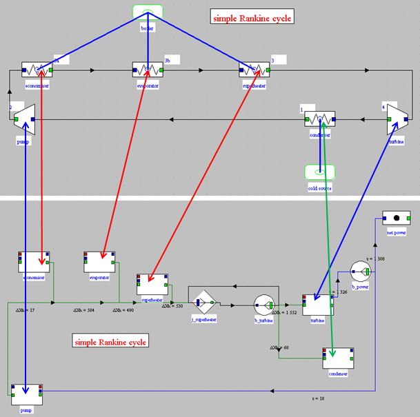
Synoptic of a regenerative reheat steam plant cycle
In this diagram, the boiler is represented in the upper part by four "exchange" processes.
At the HP turbine outlet, a divider separates the main steam flow into an extraction used to heat the water coming out of the open feedwater, while the rest of the flow is reheated and then expanded in the LP turbine.
At the bottom of the diagram, the water leaving the LP turbine is condensed, then compressed to the intermediate pressure and injected into the open feedwater where it is mixed with the extraction, which increases its temperature.
Water coming out of the open feedwater is then compressed to the maximum pressure of the cycle and directed to the economizer.
The small widget in the center of the screen summarizes the information on the energy balance of the cycle.
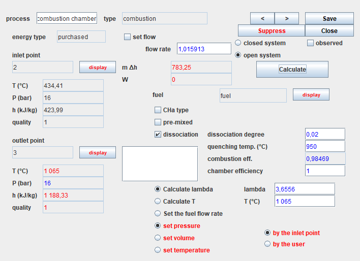
Combustion process screen
Here is a combustion chamber screen configured to take into account a CO2 dissociation rate in fumes of 2%. The temperature of the fumes is set at 1065 °C and the corresponding lambda air factor is determined.
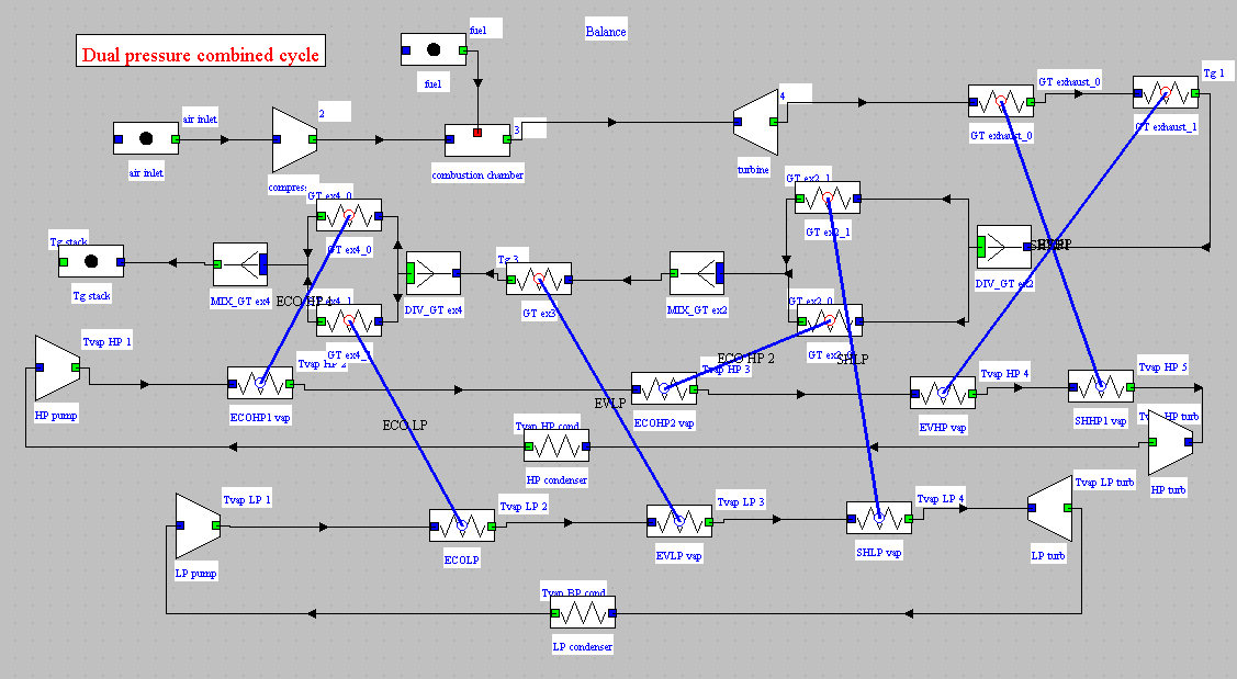
Optimization of a dual pressure combined cycle
Here is the synoptic of a dual pressure combined cycle being optimized by the pinch method. This method makes it possible to search for the configuration of the network of exchangers maximizing the electrical power produced. To do this, it draws the composite curves presented below.
At the beginning of the optimization process, the network of exchangers coupling the hot gas vein coming out of the gas turbine to the two steam circuits is not built, as in this figure. Only the "exchange" type processes of the steam circuits are defined, representing the two sets (economizer, vaporizer, superheater), and at least one gas cooling process (there are three here but it is not necessary).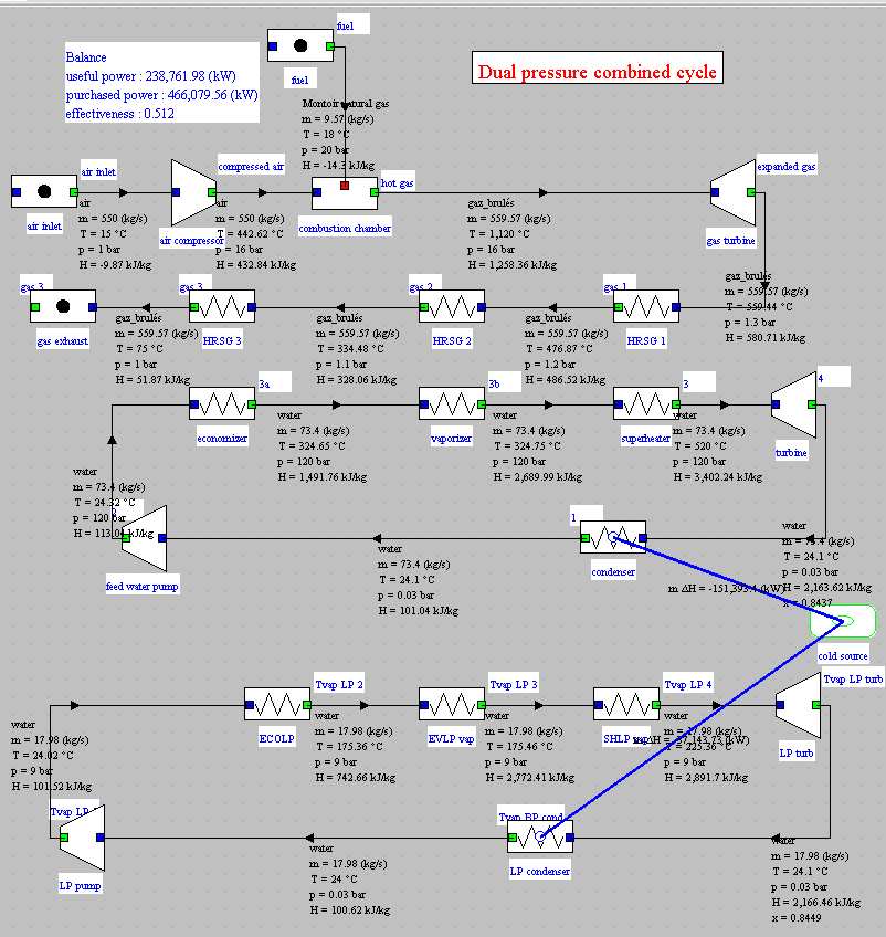
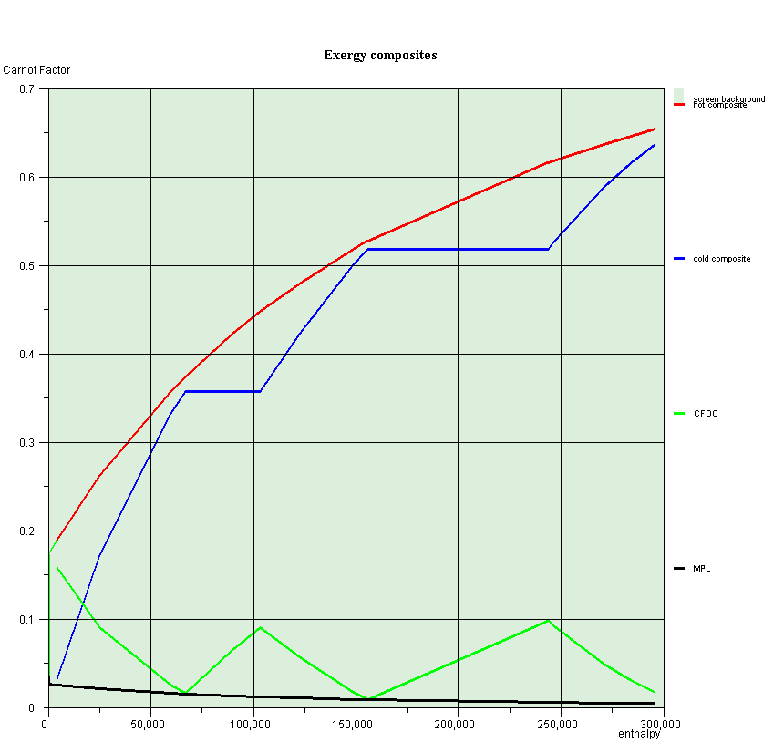
Exergy composite curves of a dual pressure combined cycle
The red composite curve represents the cooling of the gas vein coming out of the gas turbine, and the blue the heating of water and steam in steam cycles.
The green curve is called Carnot Factor Difference Curve (CFDC). It corresponds to the difference between the two composites, and the black curve is called the Minimum Pinch Locus.
On this figure, the ordinates are expressed as Carnot factor θ = 1-T0/T, T0 being the temperature of the environment.
In this case, the irreversibilities of the system are exactly equal to the area underpinned by the green CFDC.
In this figure, the optimization method made it possible to minimize the pinch between the two curves: the green curve touches the black at the two pinch points.
Productive structures
This figure shows the correspondence between the diagram of a steam cycle and its productive structure.
Such a productive structure is interpreted as follows: the steam power plant is a machine which receives an external exergy input in the boiler, and by internal recycling, exergy is provided to the pump, which are the two production units in the left of the screen.
This exergy is partly converted into mechanical form in the turbine and partly dissipated in the condenser.
The net work is the fraction of mechanical power not recycled.
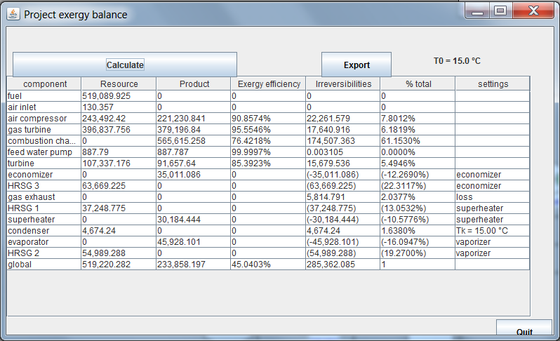
Exergy balance sheets
This figure shows the exergy balance of a combined cycle automatically established by Thermoptim thanks to the productive structure of the project.
Air treatment cycle
Here is the representation in the psychrometric chart of the air, of a summer air conditioning cycle. The outside air is first mixed with some of the indoor air that is recycled. The mixture is then cooled and condensed in a cold battery until its absolute humidity is equal to that corresponding to the supply conditions. The cooled air is then slightly warmed to lead to the desired comfort conditions.

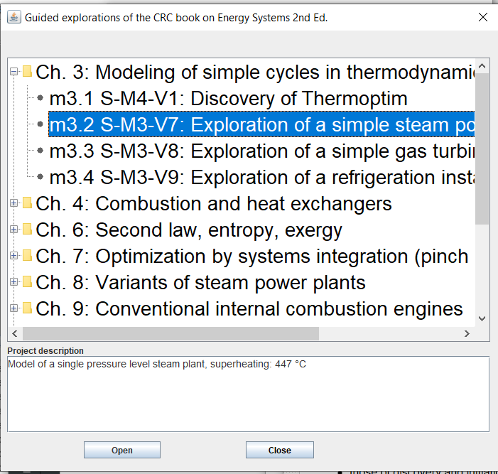
Example catalog
Example catalogs can be prepared to facilitate the loading of project and schema files.
This corresponds to Chapter 3 of the book Energy systems, 2nd Edition. On the image is selected the second guided exploration of Chapter 3.
Guided Explorations
The Thermoptim browser allows you to visualize guided explorations. Here is the tab presenting processes in the exploration dedicated to the discovery of Thermoptim.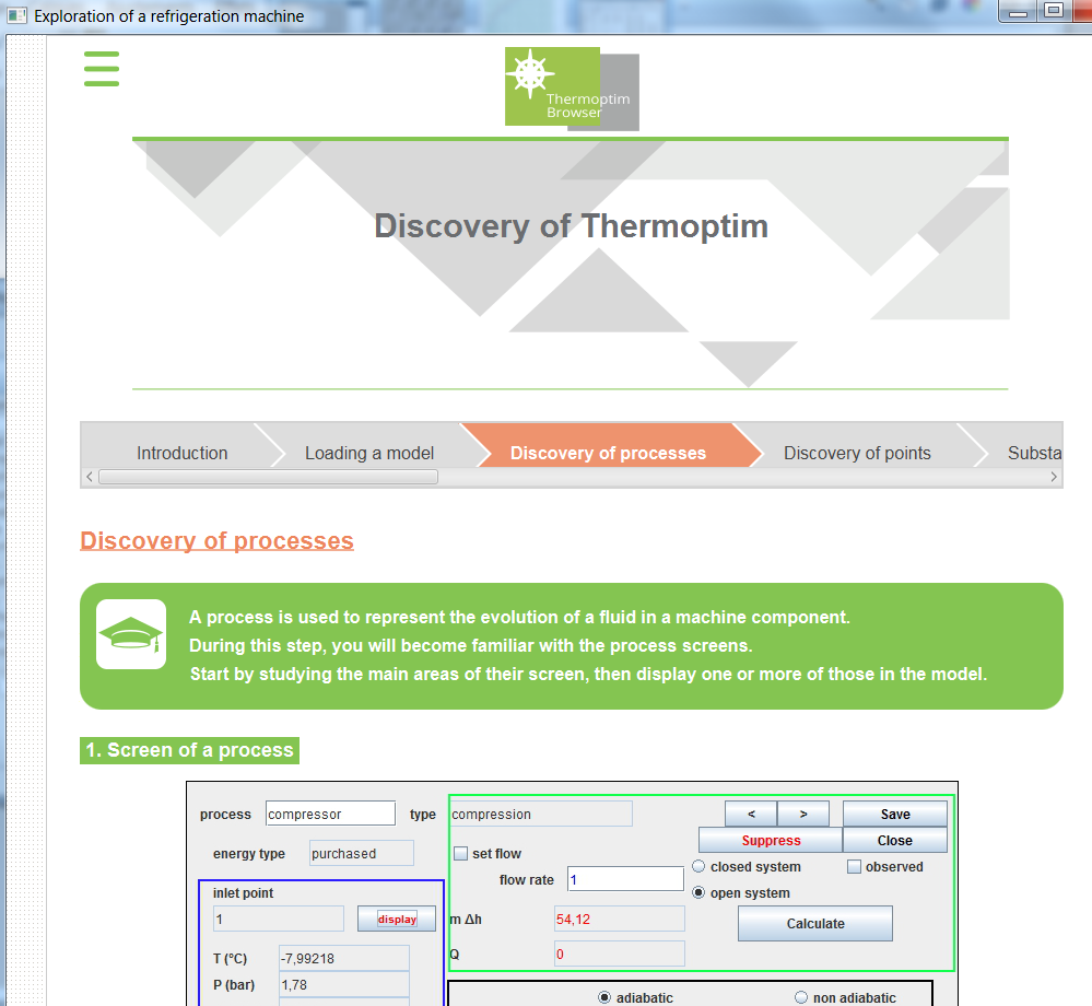
")
")